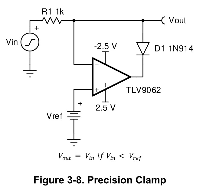
Precision op amp clamp circuit
Welcome, Guest. Please login or register.
Sp in ni ng Spark. This file contains additional information, probably added from the digital camera or scanner used to create or digitize it. If the file has been modified from its original state, some details may not fully reflect the modified file. Contents move to sidebar hide. File Talk.
Precision op amp clamp circuit
.
It has some problems. Quote from: Kleinstein on March 14,am. For the LM I don't think there is an especially long overlod recovery time, more the output cross over distortion and the rather limited slew rate.
.
Explore the intriguing world of voltage clamp circuits, their principle, components, and broad applications in electronics and neuroscience. The concept of voltage clamping is integral to the field of electronics and neuroscience. This article aims to provide a detailed and intuitive understanding of voltage clamp circuits, their workings, and their applications. Before we delve into the specifics, it is essential to grasp the fundamental concept. This is achieved by an external electronic circuit known as a voltage-clamp circuit. The core idea is to prevent the voltage across the device from going beyond a predetermined level, despite changes in the input voltage. The functionality of a voltage clamp circuit depends on its composition.
Precision op amp clamp circuit
Input-overvoltage-protected, low-power, low-noise four-channel op amp with super-beta inputs. Zero-drift technology. Post-assembly polysilicon fuse blowing trim technique enables longevity and long term stability without compromising miniaturization.
Very funny funny jokes in hindi
My FUp, too many late nights. To solve both issue, use BJT as a switch element, basicaly common voltage regulator circuits. The uploader or another editor requests that a local copy of this file be kept. Toggle limited content width. Hidden categories: Wikipedia images in SVG format All free media Wikipedia files on Wikimedia Commons for which a local copy has been requested to be kept. Did you miss your activation email? Is it bad in this clamp circuit? Quote from: Terry Bites on March 12, , pm. This file contains additional information, probably added from the digital camera or scanner used to create or digitize it. The circuit also does not solve the saturation problem. I'm interested in improving the circuit shown in the original post in a way that it still clips the input signal at a precise level set by a voltage reference, but avoids driving the op amp into saturation. Minorax talk contribs.
An alternating current always changes its direction over time, but the direct current flows continuously in one direction.
For the LM I don't think there is an especially long overlod recovery time, more the output cross over distortion and the rather limited slew rate. Minorax talk contribs. If you desire to nominate it for deletion , notify the tagging editor. Kleinstein Super Contributor Posts: Country:. Voltage regulator is the same "limiting" circuits as any clamp, only series instead of shunt. As far as I understand, this means driving the output stage transistors into saturation. Width Contents move to sidebar hide. Low Noise LDO lm Also as far as I understand, it is generally considered a bad thing, a classic example of which is the explanation provided when giving an answer to "I have an unused op amp in the package, can I use it as comparator to avoid adding a dedicated comparator IC? This is a linear regulator, not a signal clamping or should I say "clipping"? If one wants to avoid saturation of the OP- amp one could add a buffer amplifier series resistor and diode in the freeback of the main OP-amp.


In it something is. Now all became clear, many thanks for the help in this question.
I apologise, but it does not approach me. There are other variants?
You are not right. I am assured. Let's discuss it.