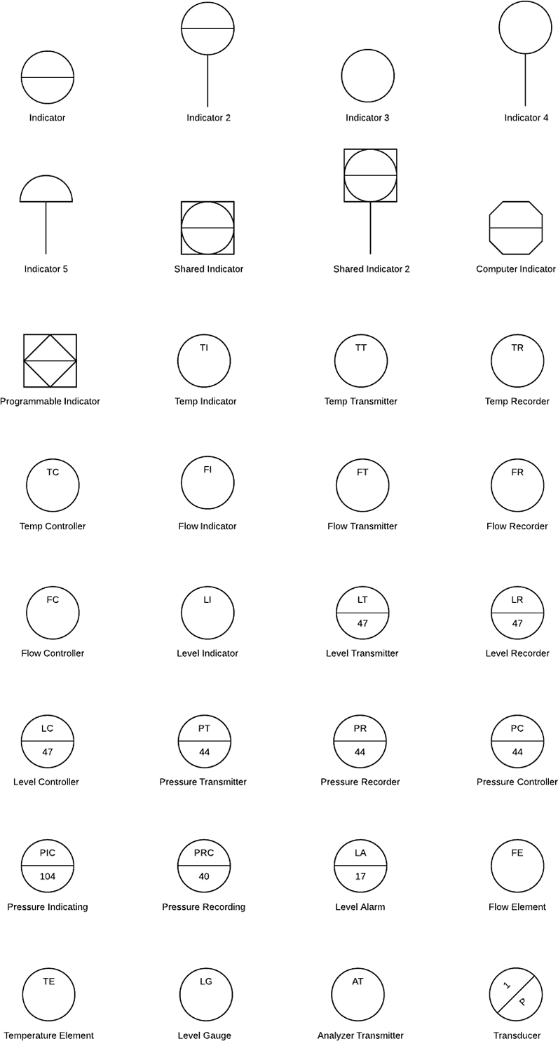
P&id symbole
EdrawMax specializes in diagramming and visualizing.
The ISA S5. Graphical representation of a temperature recorder controller of the A loop, suitable for control room mounting The following tables show: — Table 1 identifying the function of the instruments or devices — Table 2 the graphic identification of the valves — Table 3 the graphic identification of the actuators — Table 4 identifying the safety conditions of the valves and actuators. At the end will also be reported the literal and graphic symbols of the power supplies and signals of the instrumentation. The table shows the symbology of control signals for instrumentation. Author: Dott.
P&id symbole
These standardized symbols play a crucial role in helping industry professionals like engineers, technicians, and operators understand and communicate project design and process information accurately and consistently. Each symbol type has particular meanings within the context of an industry-standard notational system. These categories often have subcategories that encompass a wide range of specific symbol designs. That is why it will not be defined on the drawing. Understanding these categories and the meanings attached to their associated symbols is essential for professionals involved in designing, operating, and maintaining process systems. These can include compressors, conveyors, turbines, vacuum pumps, motors, heat exchangers, and other mechanical devices. Each type of equipment has its corresponding symbol that provides a visual representation of the equipment to be used within the system. These can include pipes, fittings, flanges, reducers, coupling, and other fluid transport devices. The piping symbols help engineers and technicians understand and depict the functional relationships between the piping components in a process system. Understanding pump symbols is essential since they provide crucial information on the functionalities of various pumps, their connections, and the direction of fluid flow within the system.
With our best regards, Projectmaterials Lugano Switzerland. Packed Tower symbol.
Piping and Instrumentation Diagrams are graphical representations of a process system. These are fundamental to every standardized engineering project. Piping and Instrumentation Diagrams detail the specific processes within a plant or industrial facility, including symbols that represent actuators, equipment, flow elements, instrumentation, piping fittings, valves. We recommend using the table of contents to navigate this comprehensive directory of common Piping and Instrumentation Diagram symbols. The symbols are organized in sections including equipment, fire and safety, flow elements, instrumentation, piping, valves, and more. Atmospheric tanks are containers for holding a variety of liquids at atmospheric pressure.
These symbols can represent actuators, sensors, and controllers and may be apparent in most, if not all, system diagrams. The standard notation, varying from letters to figures, is important for engineers to understand because it a common language used for discussing plants in the industrial world. This section covers four main types of nomenclature. The first section describes the use of lines to describe process connectivity. The second section describes letters used to identify control devices in a process. The third section describes actuators, which are devices that directly control the process. Line symbols are used to describe connectivity between different units in a controlled system. The table describes the most common lines. In Table 1, the "main process" refers to a pipe carrying a chemical.
P&id symbole
The ISA S5. Graphical representation of a temperature recorder controller of the A loop, suitable for control room mounting The following tables show: — Table 1 identifying the function of the instruments or devices — Table 2 the graphic identification of the valves — Table 3 the graphic identification of the actuators — Table 4 identifying the safety conditions of the valves and actuators. At the end will also be reported the literal and graphic symbols of the power supplies and signals of the instrumentation. The table shows the symbology of control signals for instrumentation.
Fantastik canavarlar 1 özet
The Kimray Chronicle is your source for news within the Kimray community. Level Transmitter symbol. We've broken them down into seven main groups: equipment, piping, vessels, heat exchangers, pumps, instruments, and valves. Product Create powerful visuals to improve your ideas, projects, and processes. Linear Electric. There are many p and id symbols for pumps. OR Gate symbol. Selectable Compressor symbol. Pumps are an essential part of the majority of industrial plants that need pumps, which can be used for suction, compression, moving fluid, and also for pressure control. Brackets Vessel symbol. Screw Pump 02 symbol. Helpful insights to get the most out of Lucidchart. Visit Shop.
It is also called as mechanical flow diagram MFD. During the design stage, the diagram also provides the basis for the development of system control schemes, allowing for further safety and operational investigations, such as a Hazard and operability study HAZOP.
Turbine Driver symbol. On-premises software for business. Heaters use the heat transfer process to heat water above its initial temperature using energy. Fluidized Bed Column symbol. How to read these labels? Visit Shop. Column symbol. Wastewater Treatment symbol. T First Letter Measured variable RC Later letters Functions Loop number A Suffix Functional identification Loop identification Graphical representation of a temperature recorder controller of the A loop, suitable for control room mounting The following tables show: — Table 1 identifying the function of the instruments or devices — Table 2 the graphic identification of the valves — Table 3 the graphic identification of the actuators — Table 4 identifying the safety conditions of the valves and actuators At the end will also be reported the literal and graphic symbols of the power supplies and signals of the instrumentation. Flow Monitors. No line means the instrument is installed in the field near the process.


Does not leave!