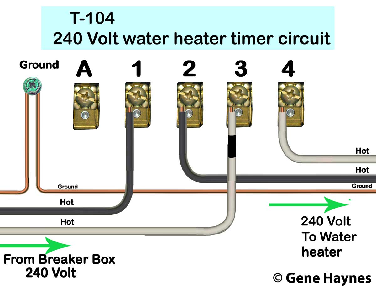
Intermatic timer wiring diagram
Running pool equipment 24 hours is usually unnecessary and expensive. Installing an Intermatic T timer is a great way to dramatically reduce run time and energy costs.
Log in. Sign up. Jump to Latest Follow. JavaScript is disabled. For a better experience, please enable JavaScript in your browser before proceeding. Joined Dec 21, I just hope I can figure out what to do when putting a 3-way switch into the 4-way outlet.
Intermatic timer wiring diagram
Log in. Sign up. Home Forums Home Improvement Electrical. JavaScript is disabled. For a better experience, please enable JavaScript in your browser before proceeding. Not convenient. As my pool has two infinity edges, it needs to have the pump running when laps are being swum. The bypass switch worked great for a decade. Then the V pool pump failed due to a scorpion intent on martyrdom that blue out the capacitors. The pool guy was not aware of the bypass switch and left it unconnected.
It only matters that one cable is on 1 and the other is on 3. Jump to latest Follow Reply.
Follow along with the video below to see how to install our site as a web app on your home screen. Note: This feature currently requires accessing the site using the built-in Safari browser. Search Everywhere Threads This forum This thread. Search titles only. Search Advanced search….
Running pool equipment 24 hours is usually unnecessary and expensive. Installing an Intermatic T timer is a great way to dramatically reduce run time and energy costs. The following steps will provide a guide on how to install the T timer. Note, timers vary with supply voltage. A T timer is used for V supply voltage. If you are using V supply voltage, you will need a T timer. The installation steps are the same for either. Toggle navigation Menu Cart My Account. Expert Advice: Chat Now or Call
Intermatic timer wiring diagram
Hide thumbs. Quick Links. Enlarged version. Troubleshooting Guide Observed Problem.
What is 40 pounds in american dollars
Ignore the first screw on the far left of your timer mechanism don't know what that wire is doing connected to it. Follow along with the video below to see how to install our site as a web app on your home screen. TM mechanism with fireman switch Buy: TM mechanism with fireman. Compare programmable timers Control water heater with programmable wall timer. For a better experience, please enable JavaScript in your browser before proceeding. One is longer than the other. For a better experience, please enable JavaScript in your browser before proceeding. RoundedRooster said:. Power only reaches cleaner timer when filter timer is ON Resources: Intermatic control centers. May 16, 2, Chapel Hill, NC. Related Articles.
.
It would be more like 6 gauge. The pump runs full time. Keep enclosure door closed to prevent overheating from getting supply of oxygen and growing into fire that can spread to local room. Hex head anchors are recommended for better traction when installing into concrete. I am installing a new Intermatic Timer -model T to replace an existing timer that no longer works. That is for sure from the documentation. Add black tape when White wire carries voltage applies to and V circuits With and Volt circuits, White wire is Neutral, and Black is Hot With and circuits, both wires are Hot, and both wires carry voltage Black tape on White wire identifies wire is Hot and not Neutral. The clock motor wires are still connected to T1 and T3 as indicated in the diagram Intermatic provided: FYI: switch controls pool light, and that circuit is fed from GFCI convenience outlet below it. After looking at the wiring diagram that HandyRon provided for us, the following wiring is correct. Yes, the loads can be spit into 10 amp and 30 amp Thread Status. Vinyl fascia. Pumps, Filters, and Plumbing Sep 22, 1poolman1.


You are not right. Write to me in PM, we will communicate.
There was a mistake