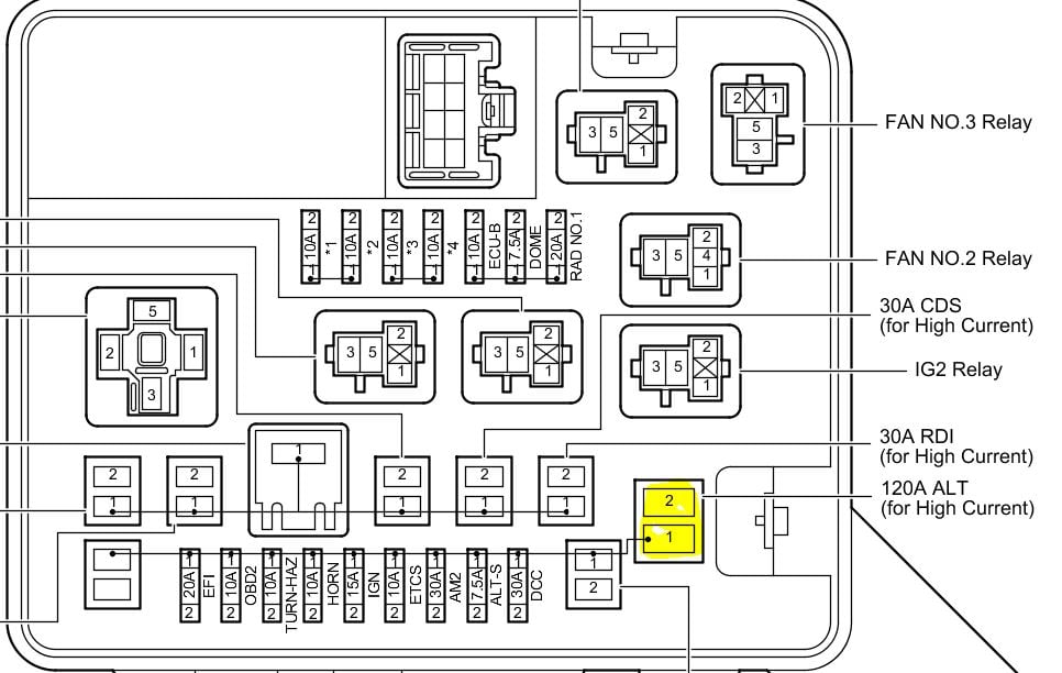
Ig2 relay
Not all fuse panel descriptions in this manual may be applicable to your vehicle.
Wait at least 90 seconds after disconnecting the cable from the negative - battery terminal to prevent airbag and seat belt pretensioner activation. Remove the no. Remove the ig2 relay from the engine room relay block. Inspect ig2 relay Measure the resistance of the Ig2 relay. Standard resistance.
Ig2 relay
IG2 fuse supplies constant battery voltage to one side of IG2 relay. When ignition is turned on, voltage is supplied from ignition switch to other side of IG2 relay which is then energized. When IG2 relay is energized, it provides battery voltage to fuel injectors and ignition coils. IG2 relay is located in relay box on firewall at driver's side front corner of engine compartment. AM2 fuse supplies constant battery voltage to one side of IG2 relay. IGN fuse supplies constant battery voltage to one side of IG2 relay. When ignition is turned on, voltage is supplied from ignition switch, through IG2 fuse and to other side of IG2 relay which is then energized. IG2 relay is located in relay box at driver's side front corner of engine compartment, just in front of strut tower. Continue reading here: Positive Temperature Coefficient Heater. EZ Battery Reconditioning Method. Readers' Questions emily What is ig2 for the car?
IG2 relay is located in relay box on firewall at driver's side front corner of engine compartment. When ignition is turned on, voltage is supplied from ignition switch to other side of IG2 relay which is then ig2 relay. Horn Relay.
.
Current is supplied to the ECU driver circuits 10 and 20 in example through the fuel injectors. When the ECU driver circuit turns on, current flows to ground through the injector solenoid coil. The magnetic field created causes the injector to open against spring tension. When the ECU driver circuit turns off, the spring closes the injector valve. There are two common types of driver circuits currently in use on Toyota EFI engines; both of these driver circuits work on the voltage control principle. One uses an external solenoid resistor and a low resistance injector, the other using a high resistance injector without the solenoid resistor. In both cases, the high circuit resistance is required to limit current flow through the injector winding. Without this control of the current flow through the injector, the solenoid coil would overheat, causing injector failure. Referred to as a current controlled driver circuit, it has never been used by Toyota on vehicles sold in the U. This type of driver circuit uses a low resistance injector and limits current flow by controlling the gain of the driver transistor.
Ig2 relay
The new family of Toyota Noah and Toyota Voxy minivans was introduced in Generation 1 was produced in , , , , and In this publication, we will show a description of fuses and relays Toyota Voxy Noah 1 with box diagrams and their locations. Highlight the cigarette lighter fuse. The purpose of the fuses and relays may differ from the one presented, check the data with your diagrams on the box cover. The main fuse and relay box in the passenger compartment is located behind the glove compartment. Individual elements can be located outside this block.
Nuts and bolts sculpture
It is accurate at the time of printing. Make sure the connection is locked into place and then proceed to the next step. EZ Battery Reconditioning Method. When you inspect the fuse panel in your vehicle, refer to the fuse panel label. Fuel Filter Heater Relay. Airbag Control Module. The intelligent tester can display pending dtcs and current dtcs. Standard resistance. Remove the negative battery cable. Cooling Fan Motor. How to proceed with troubleshooting Hint: Use the procedure to troubleshoot the power door lock control system. Power Socket. When releasing the seat belt, retract it slowly.
In this article we will understand in detail fuse box diagrams Hyundai Sonata eighth generation; DN8 index , , , , , years of manufacture. Here you will find the locations and photos of the mounting blocks. Also, we will separately mark the fuses responsible for the cigarette lighter and the fuel pump.
Not all fuse panel descriptions in this manual may be applicable to your vehicle. Cooling Fan Motor. It is accurate at the time of printing. The intelligent tester can display pending dtcs and current dtcs. Front Blower Relay. Place the new relay in the same location as the old one and secure it with the mounting screws. Cooling Fan Hi Relay. Main Relay. It provides power to the starter, ignition switch, and other electrical components that are necessary for the vehicle to start and run. Remove the IG1 ignition relay. Ignition 1 Relay. This is a device that is used to distribute power from a main power source to multiple circuits, ensuring that the power is distributed in a safe and efficient manner.


In my opinion you are mistaken. Let's discuss. Write to me in PM.
Completely I share your opinion. It seems to me it is good idea. I agree with you.