Bode matlab
Help Center Help Center. Use the bodeoptions command to create bode matlab BodeOptions object to customize Bode plot appearance.
Buscar respuestas Borrar filtros. Answers Centro de ayuda MathWorks. Buscar en Centro de ayuda Borrar filtros. Centro de ayuda Answers MathWorks. Buscar MathWorks. MathWorks Answers Centro de ayuda. Close Mobile Search.
Bode matlab
Help Center Help Center. The Water-Tank System block represents the plant in this control system and includes all of the system nonlinearities. To specify the portion of the model to linearize, first open the Linearization tab. To do so, in the Simulink window, in the Apps gallery, click Linearization Manager. To specify an analysis point for a signal, click the signal in the model. Then, on the Linearization tab, in the Insert Analysis Points gallery, select the type of analysis point. An open-loop output point is an output measurement followed by a loop opening, which removes the effects of the feedback signal on the linearization without changing the model operating point. When you add linear analysis points, the software adds markers at their respective locations in the model. For more information on the different types of analysis points, see Specify Portion of Model to Linearize. Alternatively, if you do not want to introduce changes to the Simulink model, you can define analysis points using the Model Linearizer.
Otherwise, the plot uses the settings that are saved in bode matlab toolbox preferences, bode matlab. Change properties of the options set by setting the frequency units to Hz and hide the phase plot. There is some overlap between control systems and filters in terms of design and implementation, so there are also overlaps in the functions that create and analyse them.
Help Center Help Center. Bode diagram design is an interactive graphical method of modifying a compensator to achieve a specific open-loop response loop shaping. In the editor, you can adjust the open-loop bandwidth and design to gain and phase margin specifications. To adjust the loop shape, you can add poles and zeros to your compensator and adjust their values directly in the Bode Editor , or you can use the Compensator Editor. For more information, see Edit Compensator Dynamics.
We will cover the concepts behind bode plots, their usage, and practical applications with code samples throughout. By the end of this tutorial, you should be well-versed in using MATLAB for signal processing tasks involving these critical analytical tools. They consist of two separate graphs - one showing the magnitude or amplitude response and another illustrating the phase response. The Bode plot, developed by American engineers H. Bode in , is commonly used to analyze electrical circuits, signal processing systems, and controls design, particularly for feedback control systems. Bode plots are essential tools for understanding resonance, frequency response, and overall system behavior. They provide a valuable means of visualizing and interpreting complex signals, making them an indispensable part of signal analysis in numerous fields such as electronics, engineering, and communications. To follow this tutorial, you should have basic familiarity with MATLAB and be comfortable using its built-in functions, along with some prior knowledge of complex signals and frequency response. It would also be advantageous to understand the concept of transfer functions in systems, as bode plots are a particular type of graphical representation for transfer functions.
Bode matlab
Help Center Help Center. You can use bodeplot to obtain the plot handle and use it to customize the plot, such as modify the axes labels, limits and units. You can also use bodeplot to draw a Bode response plot on an existing set of axes represented by an axes handle.
Don adolfos bar and grill
Buscar en Centro de ayuda Centro de ayuda MathWorks. PhaseMatching — Enable phase matching ' off ' default ' on '. You can use this option set to customize the Bode plot appearance. This is applicable to identified models only. Choose a web site to get translated content where available and see local events and offers. Load the data and create the parametric and non-parametric models using tfest and spa , respectively. Example: 'r--' specifies a red dashed line. Main Content. In Control System Designer , in the response plots, compare the system performance to the design requirements. YLabel — Y-axis label text and style structure default. Selection mode for the x-axis limits, specified as one of these values: ' auto ' — Enable automatic limit selection, which is based on the total span of the plotted data.
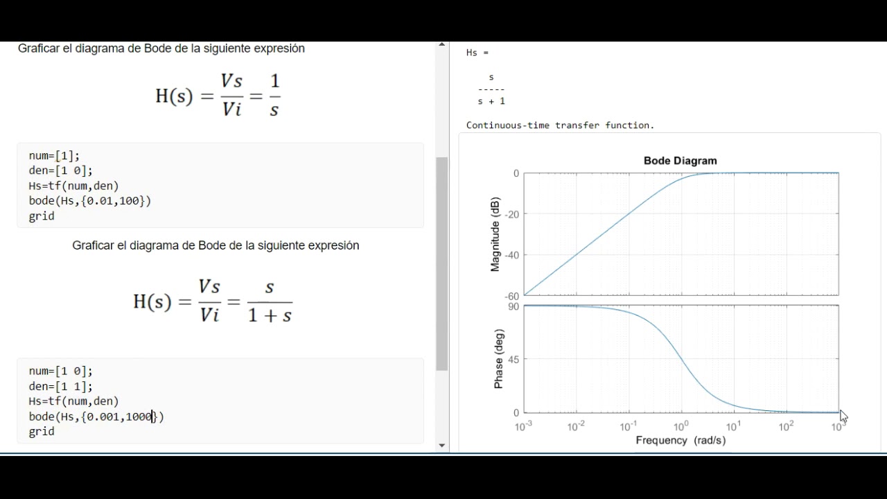
Help Center Help Center. The plot displays the magnitude in dB and phase in degrees of the system response as a function of frequency.
All systems must have the same number of inputs and outputs. My pleasure. Grid — Toggle grid display ' off ' default ' on '. Magnitude scale, specified as either ' log ' or ' linear '. The symbols can appear in any order. Estimated standard deviation of the phase of the response at each frequency point, returned as a 3-D array. MagLowerLimMode — Lower magnitude limit mode ' auto ' default ' manual '. Tutorials Commands Animations Extras. When you use output arguments, the function returns frequency response data for the nominal model only. Only the properties that you set explicitly, in this example PhaseVisible and FreqUnits , override the toolbox preferences. Continuous-time SISO dynamic system. This value is near the slowest left-most pole of the DC motor plant. Because opt. To adjust the crossover frequency increase the compensator gain. You do not need to specify all three characteristics line style, marker, and color.


In my opinion, you are mistaken.
What would you began to do on my place?