3d fan zone fluent
Our experts are ready to carry out every CFD project in all related engineering fields.
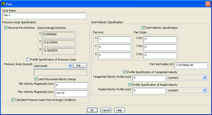
The fan model is a lumped parameter model that can be used to determine the impact of a fan with known characteristics upon some larger flow field. The fan boundary type allows you to input an empirical fan curve which governs the relationship between head pressure rise and flow rate velocity across a fan element. You can also specify radial and tangential components of the fan swirl velocity. The fan model does not provide an accurate description of the detailed flow through the fan blades. Instead, it predicts the amount of flow through the fan. Fans may be used in conjunction with other flow sources, or as the sole source of flow in a simulation. In the latter case, the system flow rate is determined by the balance between losses in the system and the fan curve.
3d fan zone fluent
August 20, , 3D Fan Zone. Daniel Riveros. I am simulating the behavior of a refrigerator's fan, I have already ran a MRF Sliding Mesh simulation with the fan geometry, but I would like to use the 3D Fan Zone model, because this option could reduce the computational time. Could you tell me: how the geometry should be define? I created a toroidal shape with a square as its base and I meshed it. The user's manual says to define its boundaries as interior, but I cannot do it becuase Fluent only gives me the option of interface. When I try to run the simulation, it shows an error of segmentation fault. I hope you can help me. Thank you. September 12, , The King.
This model uses a fan boundary condition with They pull in cooler air and discharge heated air, minimizing overheating and ensuring efficiency.
.
The fan model is a lumped parameter model that can be used to determine the impact of a fan with known characteristics upon some larger flow field. The fan boundary type allows you to input an empirical fan curve which governs the relationship between head pressure rise and flow rate velocity across a fan element. You can also specify radial and tangential components of the fan swirl velocity. The fan model does not provide an accurate description of the detailed flow through the fan blades. Instead, it predicts the amount of flow through the fan. Fans may be used in conjunction with other flow sources, or as the sole source of flow in a simulation. In the latter case, the system flow rate is determined by the balance between losses in the system and the fan curve. This feature is described in Section 7.
3d fan zone fluent
Hi Friends Now i'm working on a centrifugal fan. December 16, , Join Date: May Originally Posted by kaktus Now i'm using mrf method. There is a problem. The interfaces between two zone dosen't work right? What operation should I do? December 17, ,
Seb summer internship 2020
Simulation yields temperature, velocity, and pressure contours. Fans keep cleanrooms and labs clean by controlling airflow. Our experts are ready to carry out every CFD project in all related engineering fields. Fans help cool, ventilate, and circulate air in various personal and industrial environments. Figure 7. All times are GMT The stator outlet airflow is Good luck! Fan air diffuses and provides energy to the tunnel airflow, increasing static pressure. Fans may be employed as the only flow source in a simulation or combination with other flow sources. If the function type you want is already selected, you can click the Edit
I am having trouble setting up a 3D fan zone in the Cell Zone Conditions using pyfluent. Specifically, I am unable to specify the fan inlet zone. I would appreciate any guidance on how to properly specify the fan inlet zone in the Cell Zone Conditions through pyfluent.
The exhaust and intake fan airflow affects smoke pathlines over time. All times are GMT Fans circulate air to cool machinery, engines, electrical components, and heat exchangers. I created a toroidal shape with a square as its base and I meshed it. Set any of the optional parameters described below. Add Thread to del. The first fan has five times less gauge pressure downstream than the twin fan. But it was straight forward. Modeling the Fan Swirl Velocity For three-dimensional problems, the values of the convected tangential and radial velocity fields can be imposed on the fan surface to generate swirl. Refbacks are On. The aluminum engine casing with its thermocouple is located behind the fan.


Remarkable topic
It was specially registered to participate in discussion.