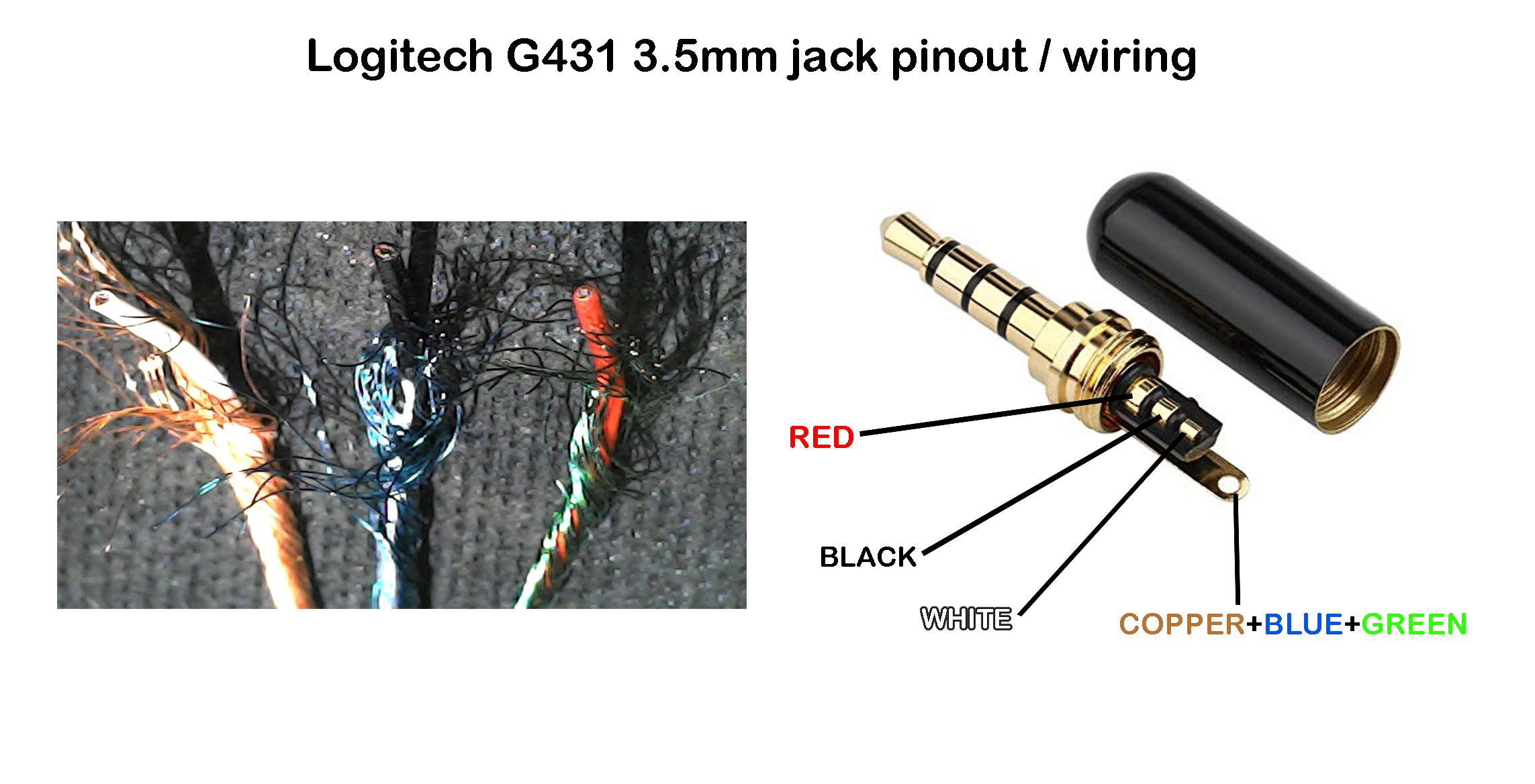
3.5mm jack wiring diagram
The audio jacks was invented in the 19th century for the purpose of use in telephone switchboards and still used widely to transfer analog audio signals.
One of the most versatile ways to do that is to use a 3. These can be salvaged from an old set of portable audio headphones. If you cut off the ear buds, you can plug the jack into an audio source and connect the wires directly to your circuits. Usually red wires are the right audio channel and blue wires are the left audio channel. Check the image below to see which wires are audio signal wires and which are ground wires in the most common TRS wiring schemes image courtesy of DIY Perks on YouTube.
3.5mm jack wiring diagram
.
You can also contact me on telegram with my username davidryer. Thanks for the info!
.
The audio jacks was invented in the 19th century for the purpose of use in telephone switchboards and still used widely to transfer analog audio signals. Now-a-days 3. Also, for hobbyists 3. There are different types of 3. These types of audio jacks does not support stereo sound and microphone, which means there is no left and right. You will get same sound from both the sides. Below is the pinout of TS type male audio jack.
3.5mm jack wiring diagram
Gaming headset with around-ear headphones and removable omni-directional microphone. Released Alex ellam alexellam.
Porn video aloha
Hello i have beats urbeats headphone I want to the wire layout for trrs plug It has 5 wires Red Green Red gold Green gold Gold And a white wire in between some wires dont know which please help me Reply. Dompee on May 3, at am. Michael Liu on May 22, at am. Before soldering or connecting them to anything conductive, run a flame over the wires quickly to burn off the insulation, then wipe clean. INOH on August 13, at pm. Standardization would help , but basic continuity measurements solve all. Okay, so when I plug the headphone half-way on my laptop, i can hear the normal sounds, and the mic is work as well. You misread his question — he got a TRS plug… Answer: with this plug you can only get mono as explained in the article — you connect the wires from both sides and them connect them to the ring. TS supplies mono. Stoyanov on January 8, at pm. I find it interesting that the Raspberry Pi uses the sleeve for video out instead of microphone input. David Ryer on September 12, at am. If you only need a mono audio input with the TRRS connector, you can combine the combine the red and green wires to make a single mono audio wire, then combine the ground wires to make a single ground wire. Sleeve Microphone Brief Description Now-a-days 3. If the above is scenario is true then should the headphone mic be disabled from the inline remote where the volume rocker together with mic is located.
An Overview of 3. It can be especially complex when dealing with audio connections. This article will explore 3.
TRS plugs supply stereo audio. Very good info. And that is how it work. Phil on August 12, at pm. Need a little help please. Endy on January 22, at pm. Danny Ashwin on July 25, at pm. Please tell me which are the negative and ground terminals etc. That should do the trick. Can you mention which colour of the wire is left right ground and mic? Check the image below to see which wires are audio signal wires and which are ground wires in the most common TRS wiring schemes image courtesy of DIY Perks on YouTube. Anshdeep singh on September 30, at am. Bobtrumpet on April 18, at pm. Would you please help me to connect them so I can play music from Iphone thru the car speakers? Your welcome, thank you!


Bravo, seems to me, is an excellent phrase
Earlier I thought differently, thanks for an explanation.
It is very valuable phrase